Suntan Will Attend FIEE 2013 in Brazil

January 8, 2013 Views
Comments 0

Suntan Technology Company Limited
----All Kinds of Capacitors

Suntan will attend FIEE 2013 - 27th International Fair of Electric and Electronic Industry, Energy and Automation.
April 1 - 5, 2013
ANHEMBI - SÃO PAULO - BRAZIL
Booth number : G120

If you will be there, we 'd like to invite you to visit our booth so as our sales can introduce our company and our products to you well.
 
Please do let us know your schedule for meeting if available or if need samples, we will prepare in advance.


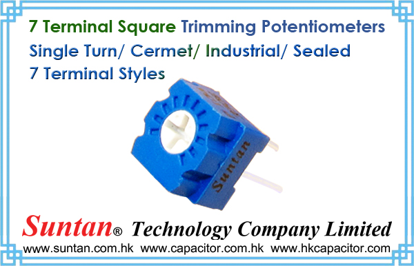
Su Suntan 7 Terminal Square Trimming Potentiometers

March 26, 2009 Views
Comments 0

Suntan Technology Company Limited
---All kinds of Capacitors

7 Terminal Square Trimming Potentiometers Features

  1. (Single Turn/ Cermet/ Industrial/ Sealed)
  2. (7 Terminal Styles)

7 Terminal Square Trimming Potentiometers Parameters download PDF files Download TSR-3323 - 7 Terminal Square Trimming Potentiometers PDF

7 Terminal Square Trimming Potentiometers - Electrical Characteristics
Standard Resistance Range 10Ω - 2MΩ
Resistance Tolerance ±5%, ±10%
Absolute Minimum Resistance ≤1% R or 2Ω
Contact Resistance Variation CRV≤1%or 2Ω
Insulation Resistance R1≥1GΩ(500Vac)
Withstand Voltage 707Vac
Effective Travel 250°


Su Suntan Capacitor Circuit

March 10, 2009 Views
Comments 0

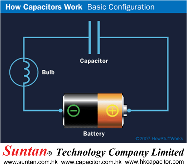
In an electronic circuit, a capacitor is shown like this:

electrical circuit

©2007 HowStuffWorks

When you connect a capacitor to a battery, here's what happens:

capacitor connected to a battery

  • The plate on the capacitor that attaches to the negative terminal of the battery accepts electrons that the battery is producing.
  • The plate on the capacitor that attaches to the positive terminal of the battery loses electrons to the battery.

Once it's charged, the capacitor has the same voltage as the battery (1.5 volts on the battery means 1.5 volts on the capacitor). For a small capacitor, the capacity is small. But large capacitors can hold quite a bit of charge. You can find capacitors as big as soda cans that hold enough charge to light a flashlight bulb for a minute or more.

Even nature shows the capacitor at work in the form of lightning. One plate is the cloud, the other plate is the ground and the lightning is the charge releasing between these two "plates." Obviously, in a capacitor that large, you can hold a huge amount of charge!

Let's say you hook up a capacitor like this:

Here you have a battery, a light bulb and a capacitor. If the capacitor is pretty big, what you will notice is that, when you connect the battery, the light bulb will light up as current flows from the battery to the capacitor to charge it up. The bulb will get progressively dimmer and finally go out once the capacitor reaches its capacity. If you then remove the battery and replace it with a wire, current will flow from one plate of the capacitor to the other. The bulb will light initially and then dim as the capacitor discharges, until it is completely out.

In the next section, we'll learn more about capacitance and take a detailed look at the different ways that capacitors are used.

Su Suntan History of the Capacitor

March 10, 2009 Views
Comments 0

Su Suntan Variable Capacitors

February 11, 2009 Views
Comments 0

Suntan Technology Company Limited
---All kinds of Capacitors

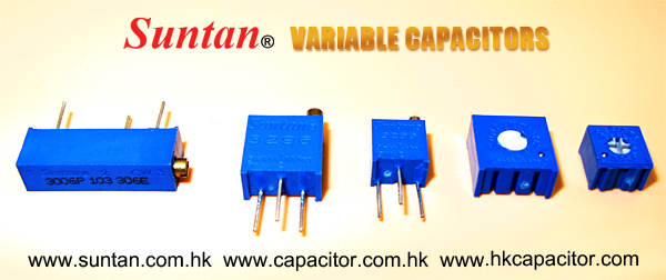
Variable capacitors are mostly used in radio tuning circuits and they are sometimes called 'tuning capacitors'. They have very small capacitance values, typically between 100pF and 500pF (100pF = 0.0001µF). The type illustrated usually has trimmers built in (for making small adjustments - see below) as well as the main variable capacitor.

Many variable capacitors have very short spindles which are not suitable for the standard knobs used for variable resistors and rotary switches. It would be wise to check that a suitable knob is available before ordering a variable capacitor.

Variable capacitors are not normally used in timing circuits because their capacitance is too small to be practical and the range of values available is very limited. Instead timing circuits use a fixed capacitor and a variable resistor if it is necessary to vary the time period.

Su Suntan Trimmer capacitors

February 9, 2009 Views
Comments 0

Suntan Technology Company Limited
---All kinds of Capacitors

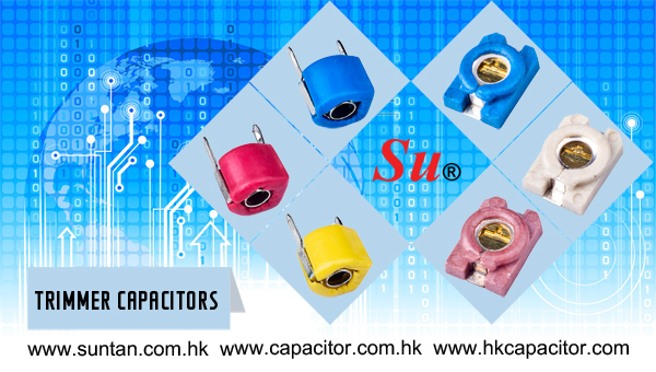
Trimmer capacitors (trimmers) are miniature variable capacitors. They are designed to be mounted directly onto the circuit board and adjusted only when the circuit is built.

A small screwdriver or similar tool is required to adjust trimmers. The process of adjusting them requires patience because the presence of your hand and the tool will slightly change the capacitance of the circuit in the region of the trimmer!

Trimmer capacitors are only available with very small capacitances, normally less than 100pF. It is impossible to reduce their capacitance to zero, so they are usually specified by their minimum and maximum values, for example 2-10pF.

Trimmers are the capacitor equivalent of presets which are miniature variable resistors.

Su Suntan Tiny Capacitors May Overcome Physical Limits of Hard Drives

February 7, 2009 Views
Comments 0

Storage—there is never enough of it. I still remember when I thought my 700MB hard drive was huge... until I tried to copy an entire CD onto it for faster access. After that, I spent a period stuck choosing music to stick on my three GB hard drive. Two weeks ago, I ditched six months' worth of simulation data because my 320GB hard drive was full. One TB of new drive later, and I'm wondering how soon it will be before I start feeling the squeeze again. Maybe never, if some of the latest research coming out of Korea and Germany bears fruit.

One of the cool things about hard drive technology is how it has actually kept pace with computer needs. The basic mechanism for hard drive storage, however, does have some fundamental limitations, which manufacturers will have to deal with fairly soon. Bits are currently stored in the orientation of tiny magnets, called ferromagnetic domains, on a hard drive platter. The smaller the domain, the easier it is for that orientation to be scrambled by temperature or stray electromagnetic fields. At a certain size, thermal photons (e.g., heat energy from the surrounding case or the underlying disk) have enough energy to flip a domain's orientation. Manufacturers will have to keep their domain sizes significantly bigger than that threshold size to ensure data integrity, which puts a ceiling on storage density, one we're rapidly approaching.

An alternative is to use ferroelectric domains. Unlike ferromagnetic domains, ferroelectric domains have a natural electric field with an orientation that can be used to represent data. Until recently, these haven't looked that attractive because they have pretty much the same limitations that ferromagnetic domains have, but they lack the cool read-out tricks. Ferroelectric materials, however, do have one big advantage over ferromagnetic materials: they can be used to make really good capacitors. This is exactly what the latest research, published in Nature Nanotechnology, is about.

Su Suntan A Bad Capacitor Story Ends Happily

January 31, 2009 Views
Comments 0

Suntan Technology Company Limited
---All kinds of Capacitors

I worked as a design engineer for an optical-telecom company that had deployed 1000 pieces of equipment worldwide. Having so many modules in the field means a trickle of returns, and it was my job to investigate the failures. One investigation taught me a wonderful lesson.

I received a module whose source of failure was easily identifiable: a charred tantalum capacitor. It failed short, making the whole multithousand-dollar module nonoperational. This surface-mount capacitor—with a 7343 footprint and 20V rating—was sitting on a 12V-dc plane. This failure rate of one capacitor in about 10,000 pieces in this time span was well below the statistical prediction. I took a picture of the fallen capacitor and considered the case closed.

In a few weeks, a customer returned a similar module with a charred and shorted capacitor in the same location. Even including this case, the failure rate was still below statistical prediction. I knew there were five more identical capacitors on the board, sitting in parallel on the same 12V-dc plane. In addition to the module's failure rate, I now had a one-in-six chance with the capacitors. So, I took another picture. I wrote a report to calm upper management, but I had a feeling that I'd better study reliability calculation in general and reliability for tantalum capacitors in particular, and the faster, the better.

In another few weeks, I received another failed module. The same capacitor looked bad. I had by now done my studying and could intimidate other people by saying long and complicated sentences about reliability, but why was it always the same capacitor? Overvoltage? Spikes? No way. The same plane contained plenty of sensitive stuff that would fry well before the capacitor even felt it. Having nothing better, I clung to the theory of excessive ripple current.

The idea of a temperature rise due to ripple current causing the failure gained traction when all three photos of the fallen capacitors revealed a common condition: almost no solder on each negative terminal. The electrical connection was still good, but there was little solder. The capacitor's positive terminal was fine with a fair amount of curvature-profiled solder. I started to promote the idea that the lack of solder had caused impeded thermal contact, but it was only wishful thinking. I calculated the worst ripple current: 10% of the maximum rating. On an operational board, I got less than 5%.

I had already dismissed other ideas—from excessive humidity to airflow turbulence. Suddenly, the picture of the layout popped up in my mind. The layout sections for the five good capacitors were identical: Vias were close to both terminals going down to an internal layer. The bad capacitor had a via at the positive terminal, but, at the negative end, there was a heavy trace going inside the footprint, beneath the capacitor, and only then outside. That's when I knew how to fit together all the pieces of the puzzle.

On the positive terminal, the solder stayed where it was supposed to, clinching the terminal to the PCB (printed-circuit board). On the negative side, however, during assembly, the melted solder drifted under the capacitor and solidified, lifting the negative end and bending the capacitor just enough to create a microcrack—a capacitor's well-known nemesis. I never felt as much excitement writing a technical report as I did the next day.
Su Suntan Electrolytic Capacitor

January 13, 2009 Views
Comments 1

Suntan Technology Company Limited
---All kinds of Capacitors

Aluminum is used for the electrodes by using a thin oxidization membrane.

Electrolytic Capacitor

Large values of capacitance can be obtained in comparison with the size of the capacitor, because the dielectric used is very thin.

The most important characteristic of electrolytic capacitors is that they have polarity. They have a positive and a negative electrode.

[Polarised] This means that it is very important which way round they are connected. If the capacitor is subjected to voltage exceeding its working voltage, or if it is connected with incorrect polarity, it may burst. It is extremely dangerous, because it can quite literally explode. Make absolutely no mistakes.

Generally, in the circuit diagram, the positive side is indicated by a "+" (plus) symbol.

Electrolytic capacitors range in value from about 1µF to thousands of µF. Mainly this type of capacitor is used as a ripple filter in a power supply circuit, or as a filter to bypass low frequency signals, etc. Because this type of capacitor is comparatively similar to the nature of a coil in construction, it isn't possible to use for high-frequency circuits. (It is said that the frequency characteristic is bad.)

The photograph on the left is an example of the different values of electrolytic capacitors in which the capacitance and voltage differ.

From the left to right:

  • 1µF (50V) [diameter 5 mm, high 12 mm]
  • 47µF (16V) [diameter 6 mm, high 5 mm]
  • 100µF (25V) [diameter 5 mm, high 11 mm]
  • 220µF (25V) [diameter 8 mm, high 12 mm]
  • 1000µF (50V) [diameter 18 mm, high 40 mm]

The size of the capacitor sometimes depends on the manufacturer. So the sizes shown here on this page are just examples.

In the photograph to the right, the mark indicating the negative lead of the component can be seen.

You need to pay attention to the polarity indication so as not to make a mistake when you assemble the circuit.

分页:[«][1][2][3][4]5[»]