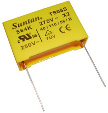
Suntan Accelerated Lift Test of Ceramic Capacitors

March 9, 2011 Views
Comments 0

The capacitor at approximately 75% of the guaranteed maximum capacitance, shall be tested for 250 hours at twice rated voltage, and at a temperature equal to the maximum operating temperature± 3°C for the respective style. At the end of this period the capacitance shall not have changed more than ±5% or ±0.5pF, whichever is greater, from its value before the life test. The I.R. shall be 1 gigaohm minimum and the“Q” at 1 MHz shall be a minimum of 40% of the initial test limit.

More..Ceramic Trimmer Capacitor

Suntan Aluminum Electrolytic Capacitor Construction

March 8, 2011 Views
Comments 0

Aluminum electrolytic capacitors are constructed from two conducting aluminum foils, one of which is coated with an insulating oxide layer, and a paper spacer soaked in electrolyte. The foil insulated by the oxide layer is the anode while the liquid electrolyte and the second foil acts as the cathode. This stack is then rolled up, fitted with pin connectors and placed in a cylindrical aluminum casing. The two most popular geometries are axial leads coming from the center of each circular face of the cylinder, or two radial leads or lugs on one of the circular faces.

More..Aluminum Electrolytic Capacitor

Suntan Zener Diodes

March 7, 2011 Views
Comments 0

Zener diodes are manufactured with zener voltages ranging anywhere from a few volts to hundreds of volts. This zener voltage changes slightly with temperature, and like common carbon-composition resistor values, may be anywhere from 5 percent to 10 percent in error from the manufacturer's specifications. However, this stability and accuracy is generally good enough for the zener diode to be used as a voltage regulator device in common power supply circuit in Figure below.

More..capacitor

Suntan Varistor includes Dipped & SMD Types

March 5, 2011 Views
Comments 0

A Varistor remains non-conductive as a shunt mode device during normal operation when voltage remains well below its "clamping voltage". If a transient pulse (often measured in joules) is too high, the device may melt, burn, vaporize, or otherwise be damaged or destroyed. This (catastrophic) failure occurs when "Absolute Maximum Ratings" in manufacturer's datasheet are significantly exceeded. Varistor degradation is defined by manufacturer's life expectancy charts using curves that relate current, time, and number of transient pulses. A varistor fully degrades typically when its "clamping voltage" has changed by 10%. A fully degraded varistor remains functional (no catastrophic failure) and is not visibly damaged.

Ballpark number for varistor life expectancy is its energy rating. As MOV joules increase, the number of transient pulses increases and the "clamping voltage" during each transient decreases. The purpose of this shunt mode device is to divert a transient so that pulse energy will be dissipated elsewhere. Some energy is also absorbed by the varistor because a varistor is not a perfect conductor. Less energy is absorbed by a varistor, the varistor is more conductive, and its life expectancy increases exponentially as varistor energy rating is increased. Catastrophic failure can be avoided by significantly increasing varistor energy ratings either by using a varistor of higher joules or by connecting more of these shunt mode devices in parallel

More..Varistor

Suntan Plastic Film Capacitors

March 4, 2011 Views
Comments 0

Plastic Film Capacitors with the high withstand-current performance of the conventional capacitors for photo flashes are used now widely for general appliances, industrial equipment, digital equipment, automotive electrical components, and hybrid cars which are required to offer high reliability and long life.

Suntan Plastic film capacitors for demanding requirements are available with Green Polyester Film Capacitor, Metallized Polyester Film Capacitor, Mini BOX metallized Film Capacitor, X2 Capacitor, Metallized Polyester Film Capacitor and Polystyrene Film Capacitor etc

In the case of film and foil types, the electrode is not applied as for the metallized capacitors, but is wound with the dielectric as a metal foil. Due to their lower series resistance, the components produced this way have excellent pulse and current carrying capability, as well as a very high insulation resistance

More..Plastic Film Capacitor

Suntan Tantalum Capacitor Dielectric Construction

March 2, 2011 Views
Comments 0

The dielectric is then formed over all the tantalum particle surfaces by the electrochemical process of anodization. To achieve this, the “pellet” is submerged into a very weak solution of acid and voltage is applied. The total dielectric thickness is determined by the final voltage applied during the forming process. Initially the power supply is kept in a constant current mode until the correct voltage (i.e. dielectric thickness) has been reached, it then holds this voltage and the current decays to close to zero to provide a uniform thickness throughout the device and production lot. The chemical equations describing the dielectric formation process are as follows:

2 Ta → 2 Ta5+ + 10 e−
2 Ta5+ + 10 OH− → Ta2O5 + 5 H2O

The oxide forms on the surface of the tantalum but it also grows into the material. For each unit of oxide two thirds grows out and one third grows in. It is for this reason that there is a limit on the maximum voltage rating of tantalum oxide for each of the present technology powders.

More..Tantalum Capacitor

Suntan Chip Trimmer Capacitors---TSC3S

March 2, 2011 Views
Comments 0

Chip Trimmer Capacitors, TSC3S Series, are miniature and ultra-thin type surface mounting device, and are recommended for miniaturization of electronic equipment.

The capacity drift after adjustment is very low and having a very thin dustproof structure, these capacitors are most suited to the fine adjustment of items.

More..Ceramic Trimmer Capacitor

Suntan Mica Capacitor Specification

March 2, 2011 Views
Comments 0

Capacitance value, when measured at 1 MHz, will be within specified tolerance limits
Dissipation factor will be less than 0.001 at 1 MHz
Insulation Resistance will be better than 100,000 Mega ohms when measured at 100 Vdc
The chips will withstand two times the rated voltage for 5 seconds without damage

More..Mica Capacitor

Suntan Aluminum Electrolytic Capacitor Polarity

February 28, 2011 Views
Comments 0

In aluminum electrolytic capacitors, the layer of insulating aluminum oxide on the surface of the aluminum plate acts as the dielectric, and it is the thinness of this layer that allows for a relatively high capacitance in a small volume. This oxide has a dielectric constant of 10, which is several times higher than most common polymer insulators. This layer can withstand an electric field strength of the order of 25 megavolts per meter which is significant fraction of that of common polymers. This combination of high capacitance and reasonably high voltage result in high energy density.

The above are the most common schematic symbols for electrolytic capacitors. Some schematic diagrams do not print the "+" adjacent to the symbol. Older circuit diagrams show electrolytic capacitors as a small positive plate surrounded below and on the sides by a larger dish-shaped negative electrode, usually without "+" marking.

More..Aluminum Electrolytic Capacitor

Suntan Construction of Aluminium Electrolytic Capacitors

February 26, 2011 Views
Comments 0

Aluminium Electrolytic Capacitors

Today electrolytic capacitors or as they are more correctly termed, Aluminium Electrolytic Capacitors are used in huge quantities. They are very cost effective and able to provide a larger capacitance per volume than other types of capacitor. This gives them very many uses in circuits where high currents or low frequencies are involved. Aluminium Electrolytic Capacitors are typically used most in applications such as audio amplifiers of all types (hi-fi to mobile phones) and in power supply circuits.

The plates of an electrolytic capacitor are constructed from conducting Aluminium foil. As a result they can be made very thin and they are also flexible so that they can be packaged easily at the end of the production process. The two plates, or foils are slightly different. One is coated with an insulating oxide layer, and a paper spacer soaked in electrolyte is placed between them. The foil insulated by the oxide layer is the anode while the liquid electrolyte and the second foil act as cathode.

In order to package them the two Aluminium foils with the electrolyte soaked paper are rolled together to form a cylinder, and they are placed into an Aluminium can. In this way the electrolytic capacitor is compact while being robust as a result of the protection afforded by the can.

There are two geometries that are used for the connection leads or tags. One is to use axial leads, one coming from each circular face of the cylinder. The other alternative is to use two radial leads or tags, both of which come from the same face of the cylinder.

The lead styles give rise to the descriptions used for the overall capacitors. Descriptions of axial and radial will be seen in the component references.

More..Aluminum Electrolytic Capacitor

分页:[«][94][95][96][97]98[99][100][101][102][103][104][105][106][107][108][»]