How to Choose Between TS13MA and TS13MB for System Boards, Display Cards, and Small Chargers
April 23, 2026 Views
Comments 0
SUNTAN TECHNOLOGY COMPANY LIMITED · ALL KINDS OF CAPACITORS

Ripple current failure in electrolytic capacitors originates from internal heating caused by AC ripple superimposed on DC bias. Ripple heating accelerates electrolyte evaporation, increases ESR drift, and reduces effective capacitance. When internal heating combines with elevated ambient temperature, service life decreases faster than predictions based only on rated voltage or ambient rating.
Radial aluminum electrolytic capacitors in output filters experience continuous ripple stress. In SMPS topologies operating above 50kHz, RMS ripple current can exceed thermal design assumptions. In LED drivers, enclosed fixtures create high ambient conditions, further elevating capacitor core temperature.
Typical field symptoms include ESR rise, capacitance drop, ripple voltage increase, LED flicker, and output instability. These failures are thermal wear-out mechanisms rather than dielectric breakdown.
P = Iripple2 × ESR
Ripple current generates heat internally in the electrolyte and foil structure. Poor thermal dissipation causes localized temperature rise. Elevated core temperature accelerates electrolyte loss and oxide layer degradation, increasing ESR, which in turn increases ripple heating in a feedback loop.
Temperature acceleration models show lifetime approximately halves for every 10°C rise. Ripple-induced core heating adds to ambient temperature, effectively pushing capacitors toward their endurance limits. Continuous operation environments such as LED luminaires and industrial power supplies show highest vulnerability.
| Parameter | Design Consideration | Selection Impact |
|---|---|---|
| Ripple Current RMS | Measured at operating frequency | Defines thermal stress level |
| PCB Thermal Zone | Distance from MOSFETs / diodes | Affects core temperature rise |
| Operating Hours | Continuous vs intermittent | Determines endurance requirement |
| Ambient Temperature | Fixture enclosure / airflow | Lifetime acceleration factor |
| Series | Endurance | Ripple Handling | Typical Use |
|---|---|---|---|
| TS14 / TS13DB | 105°C standard | General ripple | Control boards |
| TS13D2 / D4 / D8 / D9 | 5000–10000h | High ripple + high temp | LED drivers |
| TS13DI / D6 | Low impedance | High frequency ripple | SMPS outputs |
| TS13DL / D1 | Low leakage | Stable ESR | Precision circuits |
| TS13DM | Stable ESR | Audio ripple smoothing | Audio networks |
Reliable operation requires selecting capacitors based on combined ripple and temperature conditions rather than voltage rating alone.
For specification comparison based on ripple and temperature conditions, refer to official radial electrolytic capacitor specifications.
Suntan Technology · All Kinds of Capacitors.
We don’t just offer specifications. We deliver confidence for your design and sourcing decisions.
SUNTAN TECHNOLOGY COMPANY LIMITED · ALL KINDS OF CAPACITORS
When evaluating polymer aluminum electrolytic capacitors for power supply designs, engineers and sourcing teams typically focus on three practical factors:

Suntan Technology · All Kinds of Capacitors.
Polymer aluminum electrolytic capacitors designed for power supply and DC-DC applications.
Use the contact form for pricing, availability, and application inquiries.
Rather than competing purely at the premium end, the TS13 series targets engineers who need:
This makes the TS13 series a practical option when comparing polymer aluminum electrolytic capacitors for commercial, industrial, and consumer power designs.
| Series | Package | Category Temperature | Key Strengths | Typical Applications |
|---|---|---|---|---|
| TS13CP | SMD | 105°C | Compact size, low ESR, high ripple current | High-density PCB, consumer electronics, communication devices |
| TS13EX | Radial | 125°C | High temperature endurance, stable performance | Industrial equipment, automotive-related power, heat-adjacent circuits |
| TS13EY | Radial | 105°C | Super low ESR, high ripple current capability | High-efficiency power supplies, DC-DC converters, mainboard filtering |
Each model within the Suntan TS13 Polymer Aluminum Electrolytic Capacitors family is designed to support different power supply environments without adding unnecessary complexity to the design process.
The Suntan TS13CP Polymer Aluminum Electrolytic Capacitors are SMD conductive polymer aluminum solid electrolytic capacitors, designed for space-constrained PCB layouts.
Suitable for compact power supply circuits, consumer electronics, and communication equipment, where board space and assembly efficiency are critical.
The Suntan TS13EX Polymer Aluminum Electrolytic Capacitors are designed for applications where thermal stability is a primary concern. With a category temperature rating up to 125°C, TS13EX supports:
A suitable choice when evaluating polymer aluminum electrolytic capacitors for high-temperature power applications.
The Suntan TS13EY Polymer Aluminum Electrolytic Capacitors focus on super low ESR and high ripple current, supporting efficient power conversion and stable filtering.
Often considered when engineers require low ESR polymer capacitors without moving to premium-cost components.
Video: Suntan TS13 polymer series overview
Suntan Technology Company Limited – All Kinds of Capacitors For every SMD capacitor supplier, two common challenges for buyers are unstable lead time and high prices from major brands. Suntan® solves these pain points with its TS13C series, ensuring Suntan’s range supports a wide variety of capacitor sourcing needs, from consumer electronics to industrial-grade systems. By combining ▶ See demo of TS13C endurance at +105℃ and 2000H performance test.reliable capacitor delivery at a competitive price and with shorter lead times.Why Choose Suntan SMD Capacitors?
price advantage and supply stability, Suntan is a dependable partner.
1000–2000H up to +105℃.2000H load life at +105℃, optimized for SMPS.Key Benefits for Buyers and Distributors
Competitive Pricing
Same specs, more cost-effective.Reliable Delivery
Predictable lead times.Bulk Support
Flexible MOQ and order volumes.Application Highlights

Suntan Technology Company Limited – All Kinds of Capacitors
For engineers facing sourcing challenges, here’s a quick technical overview video before diving into the details. The TS14 series is Suntan’s 105°C radial electrolytic capacitor, designed to balance temperature rating, load life, and cost while ensuring IEC compliance.Key Technical Criteria
TS14 vs Market Alternatives
Applications
View Specs or Request a Sample

Suntan Technology Company Limited – All Kinds of Capacitors
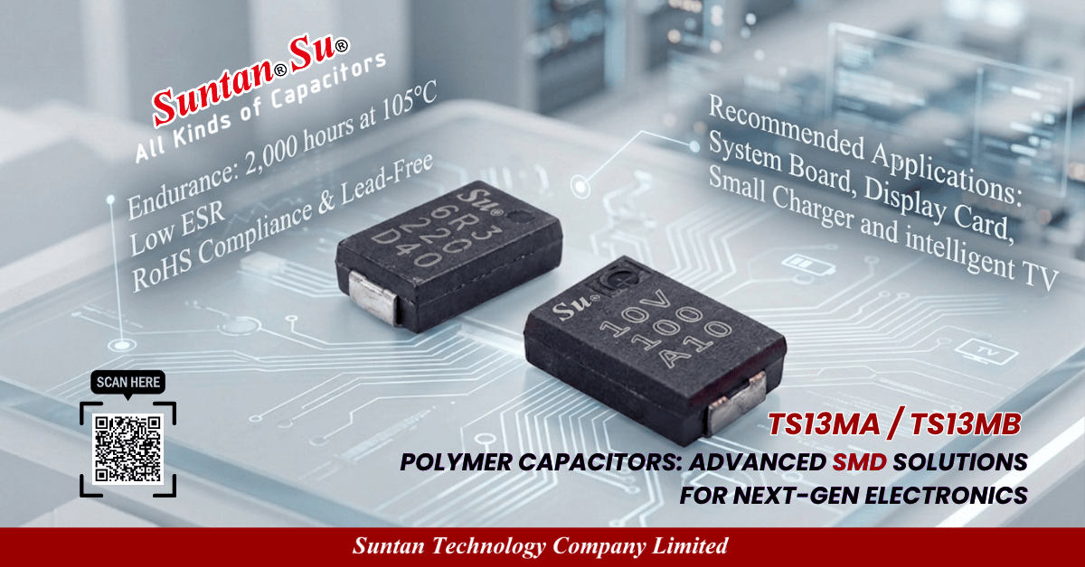
When designing compact and reliable electronic devices, choosing the right capacitor is essential for achieving stable performance and long service life. Suntan’s TS13MA and TS13MB SMD Multilayer Solid Capacitors deliver exceptional electrical characteristics in space-saving packages, making them ideal for a wide range of compact power applications.
For engineers seeking a balance between compact size, low ESR, and long-term reliability, Suntan’s TS13MA and TS13MB SMD Multilayer Solid Capacitors offer the perfect solution. Whether your design prioritizes ultra-low profile or higher capacity, these capacitors deliver dependable performance in demanding applications.
📩 Learn More or Request a Sample
View Full Product Range & Specs
Contact Technical Team for Sample Request

Suntan Technology Company Limited — All Kinds of Capacitors
When designing compact power systems, engineers often face the challenge of balancing performance, footprint, and reliability. The Suntan TS13C Series SMD Aluminum Electrolytic Capacitors are engineered to solve this problem by delivering stable performance in high-density layouts — without compromising on ripple endurance or temperature stability.
The TS13C series is ideal for applications where board space is limited, but current demands are high. Key features include:
This makes TS13C an excellent fit for compact devices such as adapters, display cards, and embedded system boards.
This modular approach ensures engineers can select the exact match for their application — whether it's for high-frequency ripple handling or extended service life in high-temperature conditions.
These capacitors are suitable for reflow soldering and ensure minimal ESR drift, even after prolonged exposure to heat cycles and ripple load.
Suntan Technology Company Limited---- All Kinds of Capacitors

In PCB designs where space is limited and operating conditions are demanding, engineers face pressure to select components that balance compactness, thermal stability, and long-term reliability — all without increasing cost or complicating the assembly process. Suntan’s TS13C Series SMD Aluminum Electrolytic Capacitors are designed to address these needs, offering practical benefits that help engineering teams reduce risk, save board space, and improve production efficiency. TS13C is available in 12.5–16mm case sizes, with voltage ratings from 160V to 450V. This allows it to replace larger through-hole capacitors in tight spaces, enabling more compact or multifunctional product layouts — especially useful in: Rated for +125°C operation and 5,000-hour load life at 105°C, TS13C offers a long service life even in thermally challenging environments such as industrial control cabinets or LED power systems. TS13C supports reflow soldering, ensuring it can be assembled with your standard SMD process — no manual insertion or rework required. With low ESR, stable capacitance, and ripple current ratings up to 320mA (at 120Hz), TS13C performs reliably under pulse load and voltage fluctuations — making it ideal for converters, inverters, and filtering circuits. Many of our clients apply TS13C in: When choosing capacitors for high-voltage or high-temp designs, mistakes can lead to redesigns, compliance failures, or unexpected costs. TS13C is built according to JIS C-5141/C-5102 standards and is RoHS and halogen-free compliant, giving your team confidence in both performance and documentation.How TS13C Helps You Build Better Products
1. Save Board Space Without Sacrificing Voltage or Performance
Your Benefit: Smaller footprint, same voltage — unlock room for more functions or smaller enclosures.
2. Withstand Harsh Conditions Over Time
Your Benefit: Lower replacement rates, fewer field failures, reduced maintenance cost.
3. Simplify Your SMT Production Line
Your Benefit: Shorter production cycles, consistent soldering quality, lower assembly cost.
4. Maintain Electrical Stability Under Load
Your Benefit: Consistent output, better filtering, and fewer design adjustments needed during prototyping.
Typical Use Cases
In each case, TS13C helps them stay within their size, temperature, and reliability requirements — while meeting cost targets.
Final Consideration: Lower Design Risk
Learn More or Request a Sample
All Kinds of Capacitors – Your Trusted Partner in Electronic Component
Suntan Technology Company Limited
---- All Kinds of Capacitors
In industrial power management, system reliability is crucial for ensuring continuous and efficient operation. Whether it's an uninterruptible power supply (UPS), power inverter, or motor drive, power systems must be designed to perform under demanding conditions. Low-ESR (Equivalent Series Resistance) capacitors are key components that help address these challenges, optimizing the performance and longevity of these systems.
Low-ESR capacitors are specially designed to minimize internal resistance, allowing them to handle higher currents with reduced power loss. This feature makes them highly effective in industrial power applications, where efficiency and reliability are paramount. When used in devices like UPS, inverters, and motor drives, low-ESR capacitors help ensure stable power supply, reduce heat generation, and extend the lifespan of critical components.
In high-frequency circuits and power conversion systems, the ability to maintain stable voltage output without excessive energy loss is crucial. Low-ESR capacitors are the perfect solution for these demands, enabling more efficient energy use and better overall system performance.
In critical applications like uninterruptible power supplies (UPS) and power inverters, a stable and continuous power source is necessary. Low-ESR capacitors are essential in these systems, helping to ensure that they can handle the high-frequency switching and variable loads without failure. These capacitors contribute to overall system reliability, reduce energy loss, and protect sensitive equipment from power surges.
In motor drives and industrial equipment, low-ESR capacitors help reduce energy consumption and improve overall efficiency by maintaining a consistent voltage output. This is especially important in environments that require continuous operation, as it reduces downtime and extends the lifespan of both power supplies and connected devices.
When selecting low-ESR capacitors for industrial applications, consider the following factors:
Low-ESR capacitors are vital for improving the reliability, efficiency, and longevity of industrial power systems. Whether you’re working with UPS, inverters, motor drives, or power converters, incorporating low-ESR capacitors can ensure stable voltage regulation, reduce power loss, and enhance overall system performance.
For high-performance low-ESR capacitors designed for industrial power applications, explore Suntan’s TS13C7 series. With exceptional temperature tolerance, long lifespan, and low ESR, Suntan’s capacitors provide the reliability you need for critical industrial systems.
Contact Us:
info@suntan.com.hk
sales@suntan.com.hk

Suntan Technology Company Limited
---- All Kinds of Capacitors
In today's rapidly advancing consumer electronics market,efficient power management is more important than ever. From portable devices to high-power electronics, every device requires capacitors that can deliver optimal performance without compromising on size, efficiency, or lifespan. This is where Suntan’s SMD capacitors, such as the TS13C4 and TS13C5, come into play. These capacitors are specifically designed to meet the evolving needs of modern consumer electronics, offering high stability, long lifespan, and low impedance—making them ideal for a wide range of applications.
The demand for consumer electronics capacitors has skyrocketed as device manufacturers continue to push for higher efficiency, smaller form factors, and better performance. Suntan SMD capacitors, including the TS13C4 and TS13C5, provide an unmatched solution to meet these challenges, enhancing everything from portable electronics to home appliances.
One of the standout features of the TS13C4 and TS13C5 is their low ESR (Equivalent Series Resistance). This characteristic significantly reduces power losses, ensuring that devices run efficiently while minimizing heat generation. Whether it's a high-power device like fast-charging power supplies or gaming consoles (TS13C5) or a low-power device like smart home gadgets and LED products (TS13C4), low ESR capacitors are crucial for ensuring stable power delivery and long-term reliability.
One of the significant benefits of Suntan's SMD capacitors is their compact SMD design, making them perfect for high-density circuit boards in portable electronics and wearable technology. This space-saving design allows manufacturers to create smaller, more efficient devices without sacrificing performance.
With high stability, long-life, and low-impedance characteristics, Suntan SMD capacitors are an essential choice for anyone working in the consumer electronics industry. The TS13C4 and TS13C5 capacitors are designed to enhance power management, minimize energy loss, and increase the overall lifespan of devices, making them the ideal choice for modern consumer electronics.
Looking to improve your products’ power efficiency, reliability, and lifespan? Suntan offers high-quality consumer electronics capacitors that deliver superior performance for today’s demanding applications. Learn more about our TS13C4 and TS13C5 capacitors and how they can elevate your devices’ performance.
Datasheet: Learn more about Suntan's SMD capacitors and explore our full range of products.
info@suntan.com.hk
sales@suntan.com.hk

Tel: (852) 8202 8782
Fax: (852) 8208 6246
Email sales@suntan.com.hk
Website www.suntan.com.hk
Teams: Suntan Teams
Whatsapp: Suntan Whatsapp