How to Order Suntan TS13AE Aluminum Electrolytic Capacitors
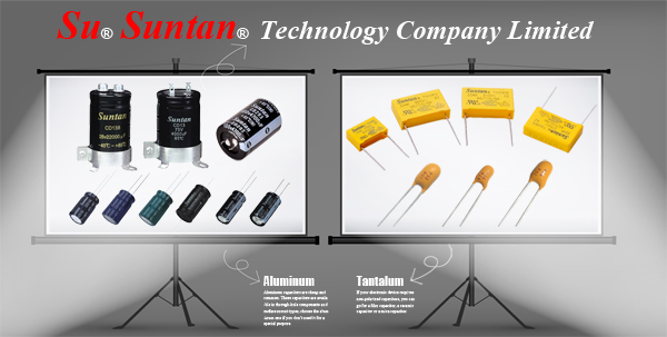
Suntan Technology Company Limited
---All Kinds of Capacitors
| Product Category | Product Description |
| Aluminum Electrolytic Capacitors | Aluminum Electrolytic Capacitors - Axial Type |
| How to Order Suntan Products | |
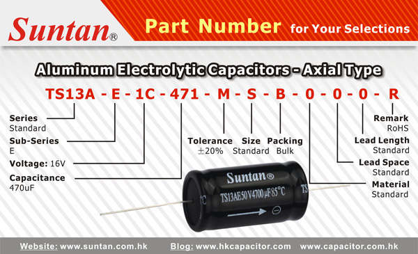
| Example: P/N | Example: Item Description |
| TS13AE1C471MSB000R | Axial E Cap 470uF 16V +/-20% 10x16.8mm 85C RoHS |
| Series | Sub- | Voltage | Capacitance | Tolerance | Size | Packing | Material | Lead Space | Lead Length | Remark |
| TS11A | E | 1C | 471 | M | S | B | 0 | 0 | 0 | R |
| Series: | TS11A |
| Sub-Series: | E |
| Voltage: | 6.3~160V.DC |
| Capacitance: | 3.3uF ~ 22000uF |
| Tolerance: | (M)+/-20% |
| Size: | S(Standard) |
| Packing: | B(Bulk) |
| Material: | 0(Standard) |
| Lead Space: | 0(Standard) |
| Lead Length: | 0(Standard) |
| Remark: | R(RoHS) |
More products details please check : http://www.suntan.com.hk/Aluminum-Electrolytic-Capacitors/Axial.html
More part number details please check : http://www.suntan.com.hk/guide.pdf