Suntan Application Guidelines for Aluminum Electrolytic Capacitors -- Circuit Design

June 1, 2011 Views
Comments 0

1.Please make sure the application and mounting conditions to which the capacitor will be exposed  are within the conditions specified in the catalog or alternate product specification (Referred as to specification here after).

2.Operating temperature and applied ripple current shall be within the specification.

The capacitor shall not be used in an ambient temperature which exceeds the operating temperature specified in the specification.

Do not apply excessive current which exceeds the allowable ripple current.

3. Appropriate capacitors which comply with the life requirement of the products should be selected when designing the circuit.

4. Aluminum electrolytic capacitors are polarized. Make sure that no reverse voltage or AC voltage is applied to the capacitors.  Please use bi-polar capacitors for a circuit that can possibly see reversed polarity.

Note: Even bi-polar capacitors can not be used for AC voltage application.

More..Aluminum Electrolytic Capacitor

Suntan Leakage Current Resistance of Aluminum Electrolytic Capacitors

May 30, 2011 Views
Comments 0

When DC voltage is applied, leakage current flows through a capacitor. The leakage current of aluminum electrolytic capacitors is larger than other types of capacitors; furthermore, the leakage current changes according to the temperature, applied voltage and application time.  If considering an equivalent circuit, the leakage current can be thought as the current flows through a resistance, which is connected in parallel to a capacitor. Leakage current becomes the power loss when capacitors are charged and self-discharge source when capacitors are discharged; therefore, it increases with error for the theoretical formulas.

The time constant in charge becomes lager than theoretical value and time constant in discharge becomes smaller than theoretical value. It is important to confirm that the capacitor meets the necessary requirements within the operating temperature range of the equipment, when using an aluminum electrolytic capacitor in a timing circuit.

More..Aluminum Electrolytic Capacitor

Suntan Principles of Aluminum Electrolytic Capacitors

May 27, 2011 Views
Comments 0

An aluminum electrolytic capacitor consists of cathode aluminum foil, capacitor paper (electrolytic paper), electrolyte, and an aluminum oxide film, which acts as the dielectric, formed on the anode foil surface.

A very thin oxide film formed by electrolytic oxidation (formation) offers superior dielectric constant and has rectifying properties.  When in contact with an electrolyte, the oxide film possesses an excellent forward direction insulation property.  Together with magnified effective surface area attained by etching the foil, a high capacitance yet small sized capacitor is available.

As previously mentioned, an aluminum electrolytic capacitor is constructed by using two strips of aluminum foil (anode and cathode) with paper interleaved.  This foil and paper are then wound into an element and impregnated with electrolyte. The construction of an aluminum electrolytic capacitor is illustrated in Fig below.

More..Aluminum Electrolytic Capacitor

Suntan Aluminum electrolytic capacitors Electrolyte

March 14, 2011 Views
Comments 0

Aluminum electrolytic capacitors are made by layering the electrolytic paper between the anode and cathode foils, and then coiling the result. The process of preparing an electrode facing the etched anode foil surface is extremely difficult. Therefore, the opposing electrode is created by filling the structure with an electrolyte. Due to this process, the electrolyte essentially functions as the cathode. The basic functional requirements for the electrolyte are as follows:

(1) Chemically stable when it comes in contact with materials used in the anode, cathode, and electrolytic paper.
(2) Easily wets the surfaces of the electrode.
(3) Electrically conductive.
(4) Has the chemical ability to protect the anode oxide thin film and compensate for any weaknesses therein. 
(5) Low volatility even at high temperatures
(6) Long-term stability and characteristics that take into consideration such things as toxicity.

More..Aluminum Electrolytic Capacitor

Suntan Aluminum Electrolytic Capacitor Construction

March 8, 2011 Views
Comments 0

Aluminum electrolytic capacitors are constructed from two conducting aluminum foils, one of which is coated with an insulating oxide layer, and a paper spacer soaked in electrolyte. The foil insulated by the oxide layer is the anode while the liquid electrolyte and the second foil acts as the cathode. This stack is then rolled up, fitted with pin connectors and placed in a cylindrical aluminum casing. The two most popular geometries are axial leads coming from the center of each circular face of the cylinder, or two radial leads or lugs on one of the circular faces.

More..Aluminum Electrolytic Capacitor

Suntan Aluminum Electrolytic Capacitor Polarity

February 28, 2011 Views
Comments 0

In aluminum electrolytic capacitors, the layer of insulating aluminum oxide on the surface of the aluminum plate acts as the dielectric, and it is the thinness of this layer that allows for a relatively high capacitance in a small volume. This oxide has a dielectric constant of 10, which is several times higher than most common polymer insulators. This layer can withstand an electric field strength of the order of 25 megavolts per meter which is significant fraction of that of common polymers. This combination of high capacitance and reasonably high voltage result in high energy density.

The above are the most common schematic symbols for electrolytic capacitors. Some schematic diagrams do not print the "+" adjacent to the symbol. Older circuit diagrams show electrolytic capacitors as a small positive plate surrounded below and on the sides by a larger dish-shaped negative electrode, usually without "+" marking.

More..Aluminum Electrolytic Capacitor

Suntan Construction of Aluminium Electrolytic Capacitors

February 26, 2011 Views
Comments 0

Aluminium Electrolytic Capacitors

Today electrolytic capacitors or as they are more correctly termed, Aluminium Electrolytic Capacitors are used in huge quantities. They are very cost effective and able to provide a larger capacitance per volume than other types of capacitor. This gives them very many uses in circuits where high currents or low frequencies are involved. Aluminium Electrolytic Capacitors are typically used most in applications such as audio amplifiers of all types (hi-fi to mobile phones) and in power supply circuits.

The plates of an electrolytic capacitor are constructed from conducting Aluminium foil. As a result they can be made very thin and they are also flexible so that they can be packaged easily at the end of the production process. The two plates, or foils are slightly different. One is coated with an insulating oxide layer, and a paper spacer soaked in electrolyte is placed between them. The foil insulated by the oxide layer is the anode while the liquid electrolyte and the second foil act as cathode.

In order to package them the two Aluminium foils with the electrolyte soaked paper are rolled together to form a cylinder, and they are placed into an Aluminium can. In this way the electrolytic capacitor is compact while being robust as a result of the protection afforded by the can.

There are two geometries that are used for the connection leads or tags. One is to use axial leads, one coming from each circular face of the cylinder. The other alternative is to use two radial leads or tags, both of which come from the same face of the cylinder.

The lead styles give rise to the descriptions used for the overall capacitors. Descriptions of axial and radial will be seen in the component references.

More..Aluminum Electrolytic Capacitor

Suntan Aluminum Electrolytic Capacitors-Snap-in type Basic design & Application

February 7, 2011 Views
Comments 0

Aluminum Electrolytic Capacitors include axial, snap-in and screw-terminal types. These capacitors offer very long life in applications requiring high ripple currents and temperatures up to 150°C. Other models have rated voltages as high as 550 VDC.

In addition to those products shown in the datasheets, KEMET can optimize the construction to offer application-specific balance between required life, temperature, ripple current, physical size, and cost.

Motor start capacitors are also offered.

A high performance electrolytic capacitor designed for automotive applications with high vibrations and high ambient temperatures.

An electrolytic capacitor with outstanding electrical performance. It is polarized with the negative pole connected to the case. The outer case has a plastic cover.

The low ESR is a result of a low resistive electrolyte/paper system. Together with the TDC thermal concept, this range has very high ripple current capability. The capacitor is suitable for both mobile and aircraft applications, with operation up to 105°C.

More..Aluminum Electrolytic Capacitor

Suntan Cautions and warnings of Aluminum Electrolytic Capacitors

January 29, 2011 Views
Comments 0

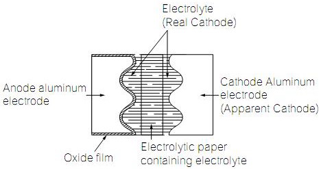
1. Aluminum electrolytic capacitors have a bi-polar structure. This is marked on the body of the capacitor. A capacitor must not be mounted with reversed polarity. The application of an AC or reverse voltage may cause a short circuit or damage the capacitor. Bi-polar capacitors must not be used in AC applications, where the polarity may be reversed in the circuits or is unknown.

2. The DC voltage applied to the capacitor terminal must not exceed its rated operating voltage, as this will result in a rapid increase of the leakage current and may damage the capacitor. It is recommended to operate the capacitor at 70 – 80% of its rated voltage to optimize its service life.

3. The ripple current applied to the capacitor must be within the permitted range. An excessive ripple current leads to impaired electrical properties and may damage the capacitor. Note that the sum of the peak values of the ripple voltage and the DC operating voltage must not exceed the rated DC voltage.

4. Capacitors must be used within their permitted range of operating temperature. Operation at room temperature optimizes their service life.

5. Capacitors with case diameter 8 mm are equipped with a safety vent. In capacitors fitted with a lead or soldering lug, the safety vent is usually located at the base of the case. It needs sufficient space around it to operate optimally. The following dimensions are recommended: for case diameter d = 8 to 16 mm, more than 2 mm; for d = 18 to 35 mm, more than 3 mm; and for d = 42 mm or more, more than 5 mm.

6. Capacitors should not be mounted with the safety vent face down on the board. Do not locate any wire or copper trace near the safety vent. Do not reverse the voltage, as this may result in excess pressure and the leakage of electrolyte.

7. Gas is released through the safety vent when the pressure inside the capacitor is too high. A gaseous liquid around the safety vent does not indicate a leakage of electrolyte.

8. The capacitor should be stored under conditions of normal temperature and in a non-acid, non-alkali environment of normal humidity. Exposure to high temperatures, for example under direct sunlight, will reduce its operating life. If the capacitor is stored in an environment containing acids or alkalis, the solder ability of the leads may be affected.

9. Containing acids or alkalis, the solder ability of the leads may be affected. The leakage current of an aluminum electrolytic capacitor may increase after a long period of storage. After such storage, the capacitor must be aged by applying the rated operating voltage for 6 – 8 hours before use.

More..Aluminum Electrolytic Capacitor

Electrical behavior of Aluminum Electrolytic Capacitor

January 20, 2011 Views
Comments 0

An electrolytic capacitor is a type of capacitor that uses an electrolyte, an ionic conducting liquid, as one of its plates, to achieve a larger capacitance per unit volume than other types. They are often referred to in electronics usage simply as "electrolytics". They are used in relatively high-current and low-frequency electrical circuits, particularly in power supply filters, where they store charge needed to moderate output voltage and current fluctuations in rectifier output. They are also widely used as coupling capacitors in circuits where AC should be conducted but DC should not. There are two types of electrolytics; aluminum and tantalum.

A common modeling circuit for an electrolytic capacitor has the following schematic:

Where Rleakage is the leakage resistance, RESR is the equivalent series resistance (ESR), LESL the equivalent series inductance (L being the conventional symbol for inductance).

RESR must be as small as possible since it determines the loss power when the capacitor is used to smooth voltage. Loss power scales quadratically with the ripple current flowing through and linearly with RESR. Low ESR capacitors are imperative for high efficiencies in power supplies. Low ESR capacitance can sometimes lead to destructive LC voltage spikes when exposed to voltage transients.

This is only a simple model and does not include dielectric absorption (soakage) and other non-ideal effects associated with real electrolytic capacitors.

More..Aluminum Electrolytic Capacitor

分页:[«][1][2][3][4][5][6][7][8][9][10][11][12]13[14][»]